Lab 1: Artemis
Objective
In this lab, we are required to get familiar with Arduino IDE and the Artemis board. We learn the basic schematics of the Artemis board and set up its function background on Arduino IDE. Then, we are able to complete tasks like blinking an LED, reading/writing serial messages over USB, displaying the outcome of the onboard temperature sensor, and documenting the loudest frequency captured by the Pulse Density Microphone.
Parts
- 1 x SparkFun RedBoard Artemis Nano
- 1 x USB C-to-C cable
Steps
-
Download and install the latest version of Arduino IDE. Since I have already installed Arduino IDE, 1.8.17 version, on my computer, I proceeded to the next step to start the setup process.
-
Install the Arduino core for Apollo 3. I followed the instructions shown on the “Artemis Development with Arduino” to first adjust the Additional Board Manager URL in Preferences, and install the SparkFun Apollo 3 board package. It took a few minutes to finish the installing process.
-
Implement “Example: Blink It Up!” shown in the introduction page. In this step, we need to blink the LED on the Artemis board by running the example file ‘Blink’. I compiled the file and uploaded it to the board, and the blue LED starts blinking as shown in the following video.
-
Run Example2_Serial in File-> Examples-> Artemis Examples. The path is slightly different from the instruction, but I was able to find the serial example in File-> Examples-> Apollo 3-> Example04_Serial. In this example, the baud rate is set to 115200, and it echoes the serial data that user writes on the serial monitor. I also make sure that the serial monitor is set to the same baud rate as listed to display the message correctly. As shown in the video below, it is able to display what I just entered on the serial monitor, which means the message is read and write as expected through the USB port.
-
Run the AnalogRead example. The example is able to read the temperature captured by ADC channels. On the serial monitor, we can see the raw ADC counts from the die temperature sensor from the board. The change of the temperature takes some time to reflect on the numbers. The first video shows the temperature before warming up the chip. The temperature data collected is in the range of 32200-32300. After I hold on the chip for a while, the temperature increases to around 33000.
Here is the demo before warming up the board:
Here is the outcome after warming up the board:
-
Run the MicrophoneOutput example. The example can capture the loudest frequecy from the embedded microphone. As the music starts playing, the loudet frequency changes based on the sound received.
Additional task:
-
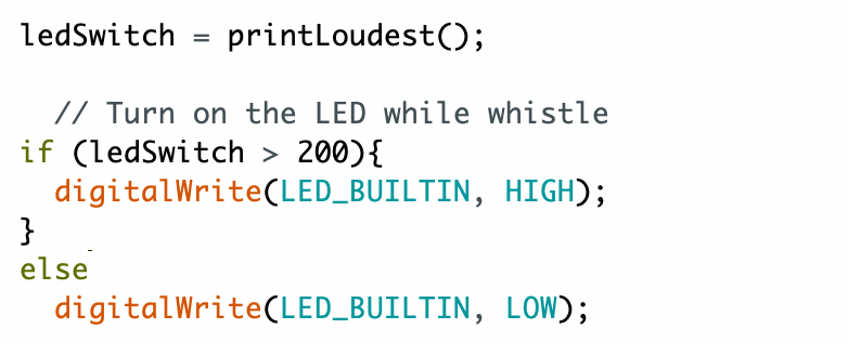
Program the board to turn on the LED when you whistle, and off otherwise. I added an variable ledSwitch to record the return value of the loudest frequency. If the loudest frequency is higher than 200, the LED is set to HIGH. If not, it is set to LOW. 200 is a rough measurement cap of frequency with no specific sound appeared while measuring.
