Lab 5: Open Loop Control
Objective
In this lab, we want to change from manual to open loop control of the car, which means the car motion will be pre-programmed to perform the required tasks. We learn how to program motor drivers to control the car movement and understand the effectiveness of the PWM singals.
Prelab
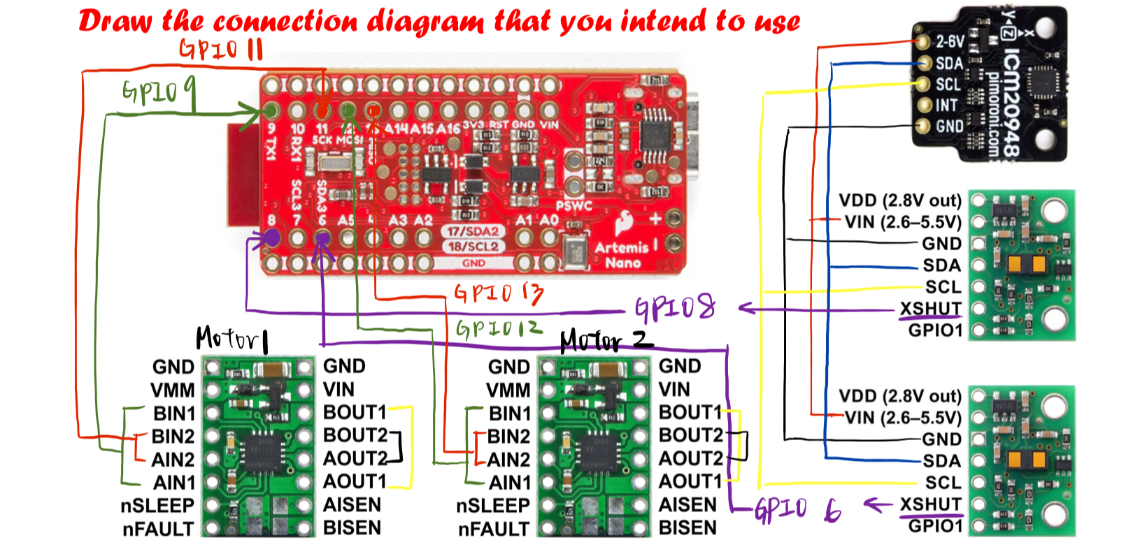
We intend to parallel couple the two inputs and outputs on each motor driver, which means we use two channels to drive one single motor. This enables us to drive twice the average average current without overheating the chip. As for the circuit design, I soldered A, B channels with the same input and output numbers together. Since we need to drive pwm signal from the Artemis board to the motor drvier, I chose GPIO pin 9, 11, 12, 13 to connect to the inputs of two motor drivers respectively. It’s also better to power the Artemis board and the motor drivers/motors from separate batteries since the range of the voltage required to power up the motors is higher than the voltage for Artemis board. If they use the same battery, the Artemis board may fail.
Lab Procedure
- First, I connect the power and signal input to a motor driver and use analogWrite to generate PWM signals from the Artemis board. For now, dc power supply is used to power up the motor driver for debugging feasibility. I use GPIO pin 9 and 11 to generate PWM signal from 0 to 255, and then ramp it down by
 for(int i=0; i<=255; i++){
   analogWrite(ain1, i);
   delay(10);
 }

 for(int i=255; i>=0; i--){
   analogWrite(ain1, i);
   delay(10);
 }
As shown in the video, the duty cycle goes from 0 to 100% and decreases back to 0% gradually in the oscilloscope.
-
I connected one motor driver to a motor, and power it from an external power supply to see the outcome of driving a motor from the current code. At first, I only heard buzzing sound but the wheels did’t rotate at all. I realized the voltage may not be high enough to drive the motor, so after I ramped the power supply up to 6 V, the wheels started to rotate. This proved that the wiring is all good, so the next step is to power the motor with the battery.
-
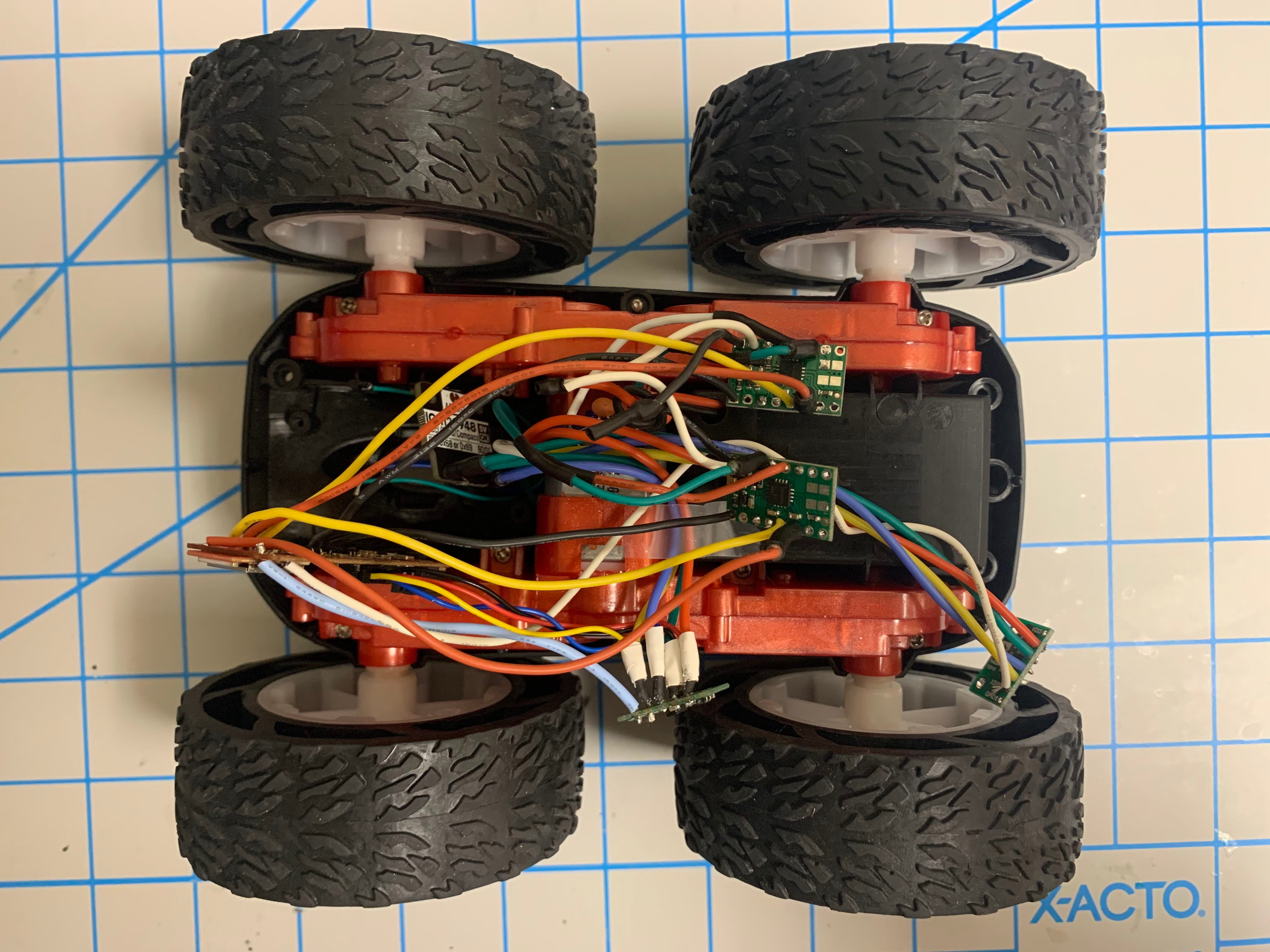
After checking that both motor drivers function as expected, I took the car apart to remove the unwanted parts and planned out the wire paths to hook up all the components. I removed the original PCB board and the wires connected to the LEDs and motors since I’ll replace the PCB with the Artemis board. Motor drivers are connected to the Artemis board as shown in the prelab circuit design, and the VIN and GND pins for the power source are powered by a 850 mAh battery. The Artemis board is placed in the slot where the PCB board originally sat in and is powered a 650 mAh battery on its own. Also, I resoldered some parts to adjust the length of the wires to fit onto the car stably. Tapes are used to fasten all connections, including the previous sensors, in place while testing.
-
When the whole car can be powered by batteries, I wrote a simple move forward code to test the lower limit for which each motor still turns while on the ground. It turned out that the pwm input needs to be at least 42 or 43 to drive the car to move as expected. Sometimes 40 stills works, but the outcome is unstable and may only drive one side of the wheels.
-
I recorded a short video to perform that the car can move at a fairly straight line at low speed. It drifted a little bit because the starting time of the two wheels differed at such low signal. The car can move straight easily at a higher speed, which will be shown in the next video.
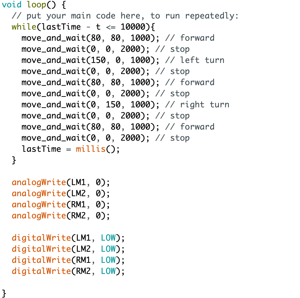
- For the final open loop, untethered control of the car, I wrote a program that allows the car to go forward and turn left or right based on the script. For the
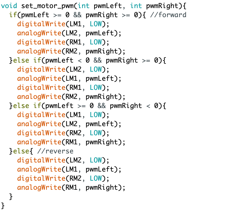
move_and_wait(int pwmLeft, int pwmRight, int duration)function, it basically separates the PWM signals for the left or right motors and sets the duration time for each step. As for theset_motor_pwm(int pwmLeft, int pwmRight)function, it deals with the digitalWrite and analogWrite of the motor to drive or stop a motor. Although I only used the forward instruction so far, I implemented the reverse version of the motion for all possible instructions. All the detailed code is provided below along with the final running and turning car!

Additional Tasks
-
According to the Arduino documentation, the frequency that analogWrite function generates differs between different boards and pins. I didn’t find the exact PWM frequency for Artemis board from the datasheet, so I refer to Arduino Uno as an example. For Arduino Uno, the PWM frequency for most pins is 490 Hz, while pin 5 and 6 have a higher frequency at 980 Hz. I think it is fast enough for the current usage of the motors. However, the benefits for a faster PWM signal is to have high motor efficiency, fast control response, low motor torque ripple and so on.
-
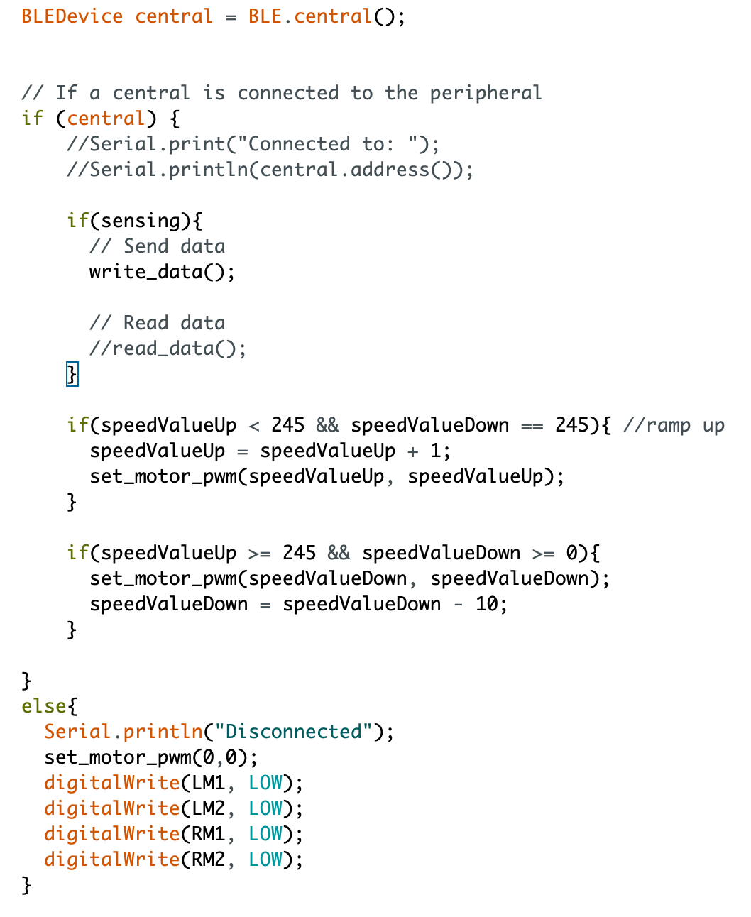
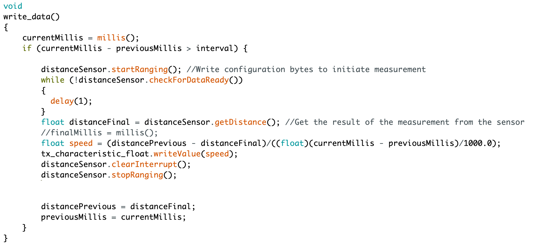
To document the speed range of the car, I use the ToF sensor from the previous lab and combine the bluetooth implementation in lab 2 with my motor code. In this way, I can get the speed data from my computer via the bluetooth notification handler. I updated the code in loop(void) as below, where the write data function is the same as in lab 4 and
speedValueUpandspeedValueDownrepresent the speed variables for ramping up and down respectively.set_motor_pwm(speedValue, speedValue)is the same function shown in the previous section. The car can go up to 245 in pwm signal and stops before running into the wall.
As for the data collection via the bluetooth connection from my computer, I used the same notification handler in lab 2 to write the speed value into the array and print out the float value.

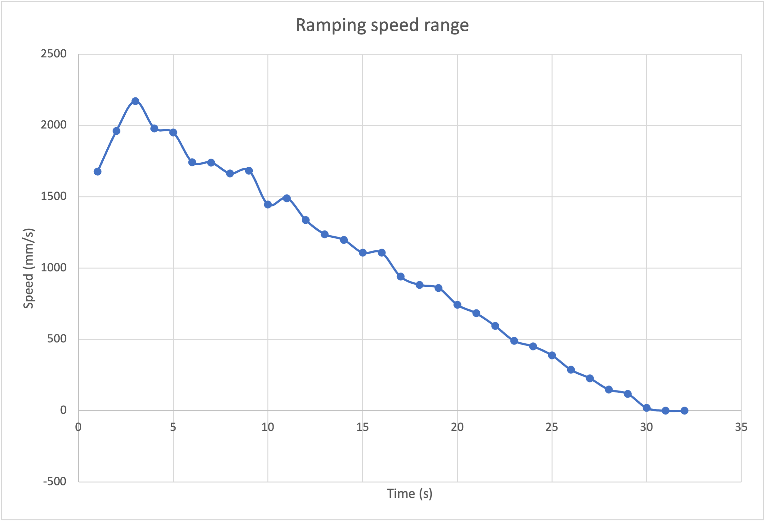
I placed the car 3.5 m away from the wall since the data range of the ToF sensor is within 4 m. From the test, the highest speed I achieve is 2171.43 mm/s. However, the notification handler seems to have a time delay to print out the initial speed ramping values, so I didn’t capture the speed increase trend for the sensor. As shown in the following picture, the speed range spans from 0 to around 2200 mm/s. It also demonstrates a linear relation between the speed and time in the measured time period. A video is also recorded to show how I implemented the test!
Reference
- analogWrite() - Arduino Reference: https://www.arduino.cc/reference/en/language/functions/analog-io/analogwrite/
- K. Shirabe et al., “Advantages of high frequency PWM in AC motor drive applications,” 2012 IEEE Energy Conversion Congress and Exposition (ECCE), 2012, pp. 2977-2984, doi: 10.1109/ECCE.2012.6342519.